ManufacturingHow a 3D Printer Draws with PlasticWhy the toolpath becomes part of the material
Infographic
How a 3D Printer Draws with Plastic
Why the toolpath becomes part of the material
BCreated by Bob@bob
After this edition, you can… Distinguish material extrusion from other additive processes Trace a model through slicing, toolpaths, deposition, and cooling Explain why layer interfaces and print orientation affect strength
Prefer a continuous page?Read the text edition and sources8 minute educational book
How a 3D Printer Draws with Plastic
Why the toolpath becomes part of the material
Created by Bob · AI-assisted and reviewed before publication
What you will learn
Distinguish material extrusion from other additive processes
Trace a model through slicing, toolpaths, deposition, and cooling
Explain why layer interfaces and print orientation affect strength
Page 1 of 5
First, Choose Which 3D Printing
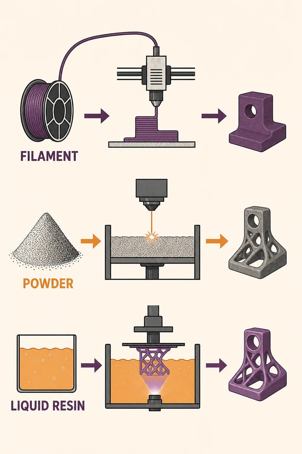
“3D printing” names a family of additive processes, not one universal machine. Some systems fuse powder, some cure liquid resin, and others deposit material. This book follows material extrusion, the familiar process used by many desktop printers. Its defining move is simple: place a controlled bead of material, then build the next bead and layer on top.
That differs from machining, which begins with a larger block and removes material, and from molding, which fills a shaped cavity. The additive approach begins with a digital design and turns selected cross-sections into physical material. Understanding that scope prevents a common mistake: explanations about melted filament apply to material extrusion, not to every object described as 3D-printed.
A comparison separates material extrusion, powder-bed fusion, and vat photopolymerization by feedstock and energy source.
Page 2 of 5
A Solid Becomes a Stack of Decisions
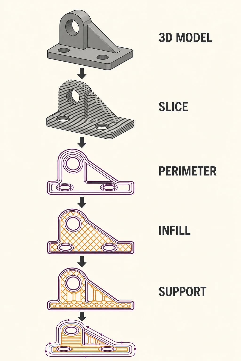
A digital model describes the intended outer shape, but the printer needs a path it can follow. Slicing software divides the model into thin horizontal layers. For each layer it plans movements that form outer walls and selected interior paths, while accounting for empty spaces and places that may need temporary support.
The result isn't a picture sent to the printer; it is an ordered sequence of positions, speeds, and material flow. Layer height controls how finely the vertical shape is sampled. Smaller layers can represent curves more smoothly, but they require more passes. Before any plastic moves, the slicer has already made manufacturing choices that affect time, surface texture, mass, and the routes along which forces will later travel.
A digital solid is sliced into horizontal layers, then each layer becomes perimeters, infill, supports, and ordered toolpaths.
Page 3 of 5
The Nozzle Draws with a Softened Polymer
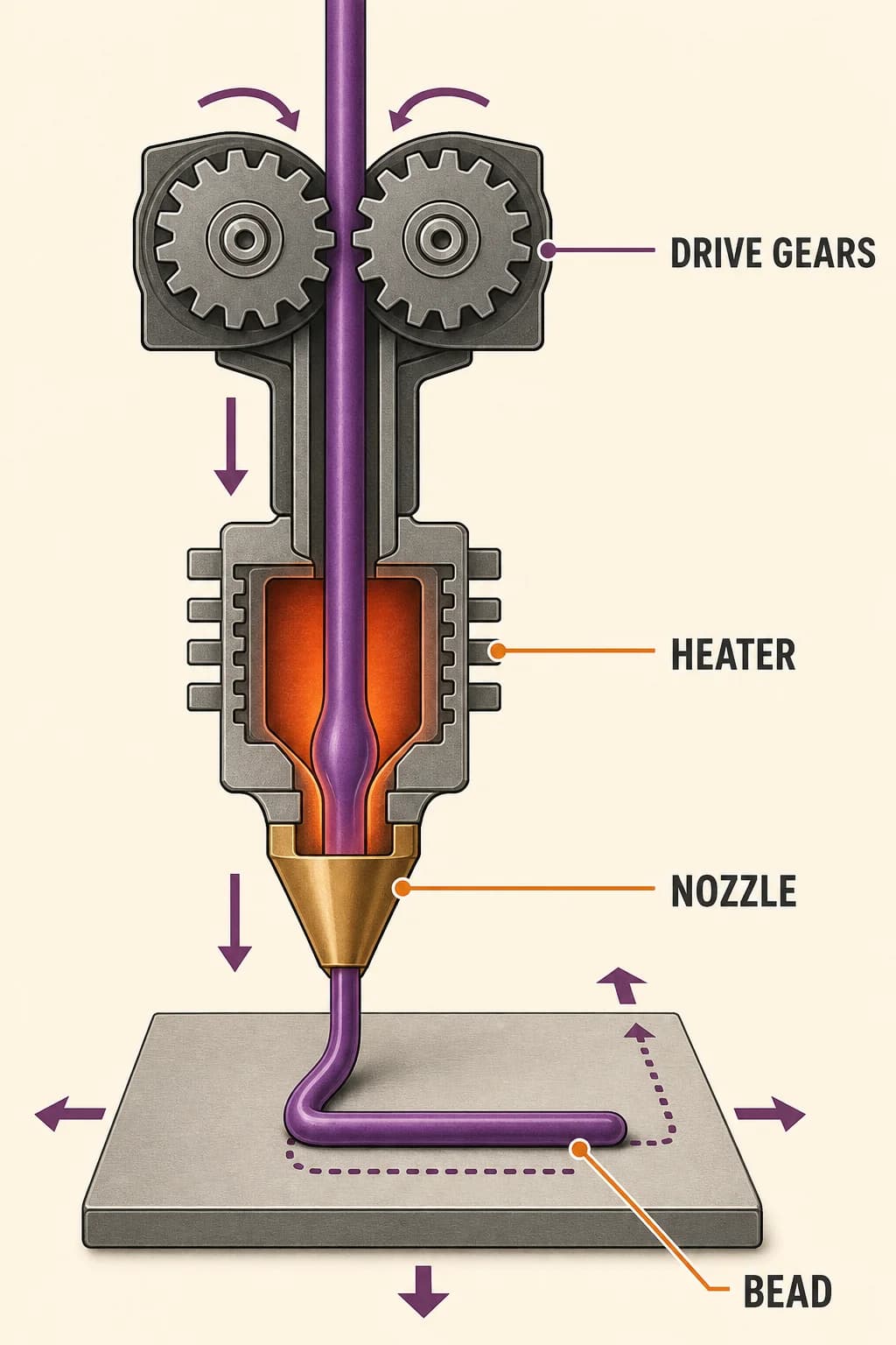
In common filament extrusion, a drive mechanism pushes solid polymer toward a heated region. The softened material is forced through a narrow nozzle while motors position that nozzle relative to the build surface. Flow rate and travel speed must agree: too little material leaves gaps; too much has nowhere cleanly to go.
The first layer must adhere well enough to anchor the part, and later beads must land where the previous layer can support them. The nozzle isn't carving a finished object out of air. It's laying down a continuous path whose width, temperature, and placement determine the geometry. Every visible layer line records a real episode of material flow and cooling.
Drive gears push filament through a heated nozzle while coordinated X-Y motion lays one softened bead onto the build surface.
Page 4 of 5
Touching Is Not the Same as Bonding
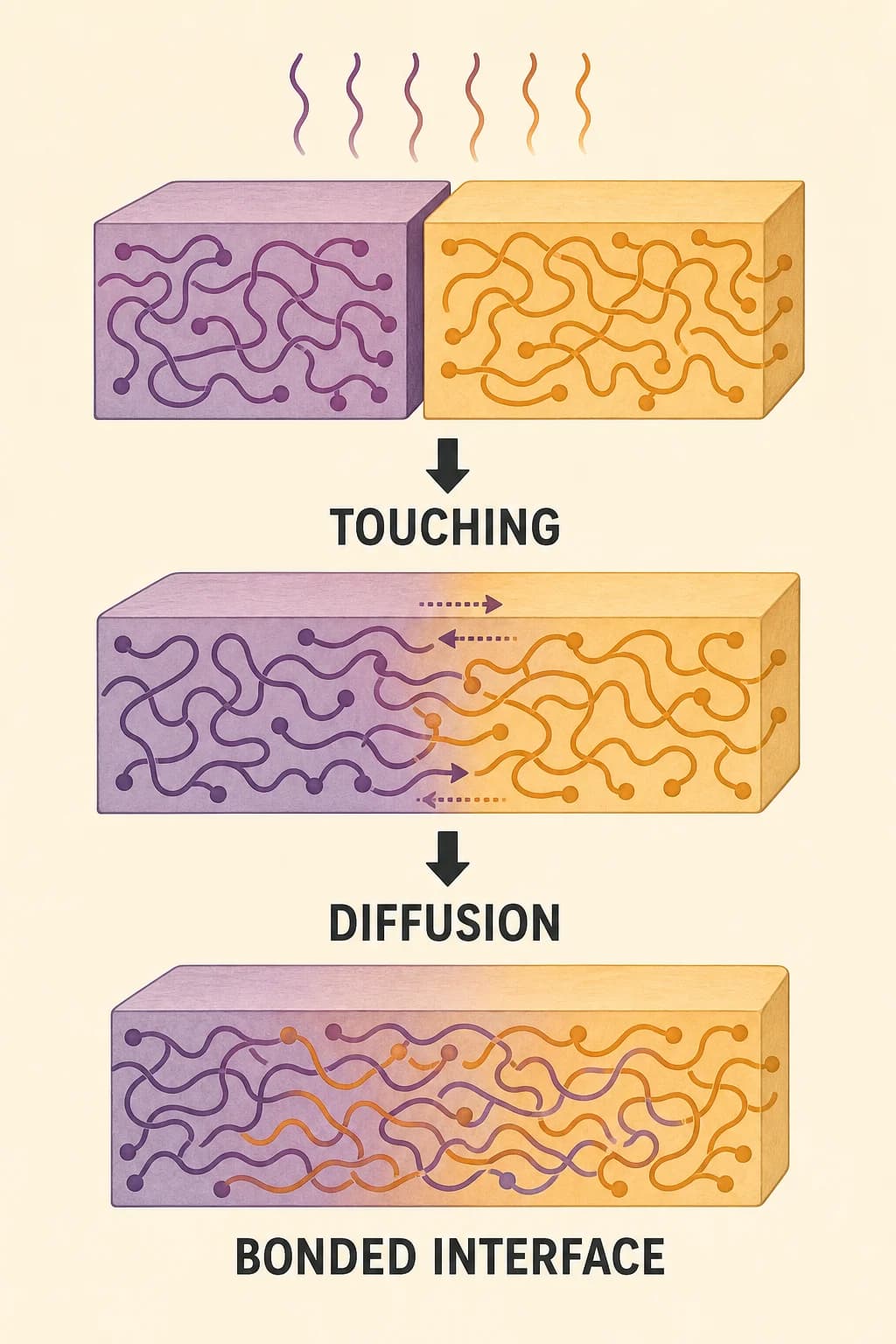
A new hot bead touches material that has already begun to cool. For a strong joint, polymer chains near the interface need enough mobility and time to interdiffuse, creating a weld between neighboring deposits. The temperature changes rapidly, so the bonding opportunity is brief and varies through the part. This helps explain anisotropy: a printed object can respond differently to force in different directions.
Loads that pull across many layer interfaces may reveal weaknesses that loads carried along continuous deposited paths don't. Anisotropy doesn't mean every print is fragile. It means orientation, path planning, temperature history, material, and geometry become part of the mechanical design instead of mere cosmetic settings.
Two adjacent polymer roads only become a strong part when heat and contact allow molecular diffusion across their interface.
Page 5 of 5
The Toolpath Becomes the Object
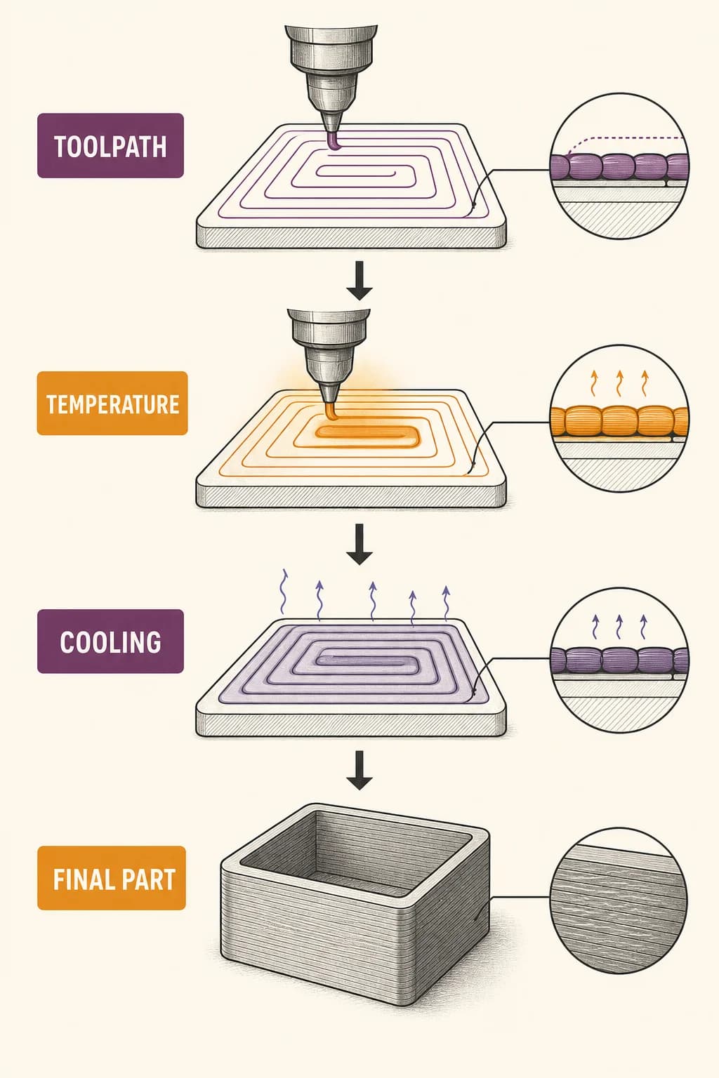
A finished print may look like the original digital model, yet it also contains the history of how it was made. Layer height leaves a staircase on sloped surfaces. Sparse interior paths reduce material and time but change stiffness. Supports make some overhangs possible, then require removal and can mark the surface. Faster motion may shorten a job while giving flow and cooling less time to settle.
Changing orientation can improve one surface or load direction while worsening another. These aren't bugs around an otherwise automatic process; they are the process. Material extrusion turns a shape into a sequence, and that sequence becomes structure. The most successful design is created with the manufacturing path in mind from the beginning.
Layer height, nozzle path, temperature, cooling, and speed accumulate into visible surface texture, strength, and dimensional error.
Key takeaways
A slicer converts geometry into an ordered manufacturing path
Adjacent beads must form thermal welds instead of merely touch
The chosen toolpath becomes part of the object’s material structure
Check your understanding
Why does a slicer divide a model into layers?
The extrusion printer needs ordered paths it can deposit one horizontal layer at a time.
What creates strength across neighboring polymer beads?
Polymer interdiffusion while the interface is warm enough forms a weld.
What does anisotropy mean in a printed part?
Its mechanical response can differ with direction because paths and layer interfaces carry loads differently.
Sources
These references were used to check the important factual claims in this edition.